This section makes frequent use of data contained in the Technical Requirements.
All relevant sections of the Technical Requirements Data collection should be completed or known before commencing with the steps in this section.
AXL Configuration
VSM uses AXL API to collect data from CUCM; this can be achieved by creating a user with AXL Capabilities within CUCM.
Enable AXL Service
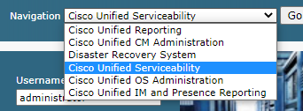
Browse to the CUCM, then select "Cisco Unified Serviceability" from the navigation menu.
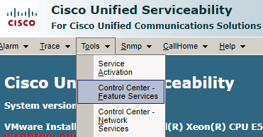
Go to Tools > Control Centre - Feature Service.
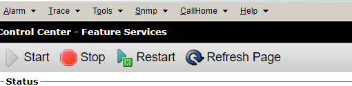
Click on the select server dropdown menu and choose the CUCM Publisher. Then click 'Go'.
Make Sure AXL Web Service status is started.

If the AXL Web Service is deactivated or stopped, start it from the top of the page.
Create CUCM AXL User
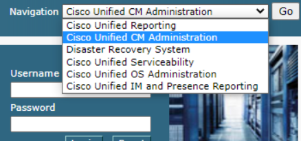
Browse to the CUCM, then select 'Cisco Unified CM Administration' from the navigation menu. Once selected, click 'Go'.
Create AXL privileged Access control group
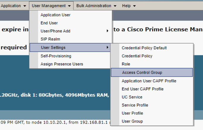
Go to User Management > User Settings > Access Control Group.
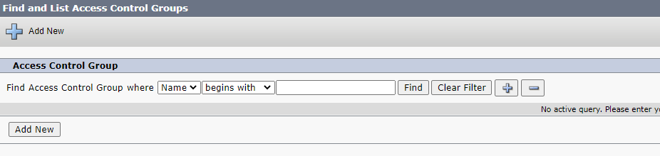
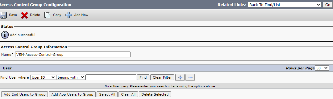
Click the "Add New" button to create a new Access Control group.
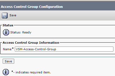
Enter an Access Control group name and click save, e.g. VSM-Access-Control-Group.
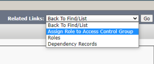
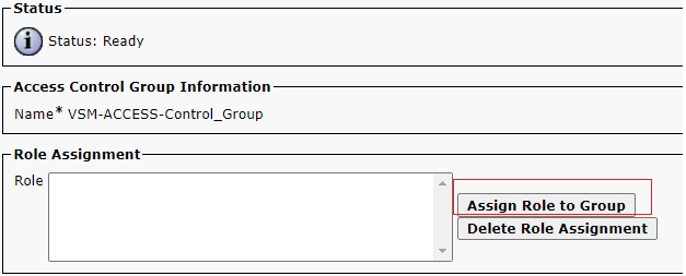
In the top right corner, click on the related links dropdown menu. Next, select the "Assign Role to Access Control Group" option, then click 'Go'.
Under 'Role Assignment', click the "Assign Role to Group" button.
A page will appear with a list of all available roles.
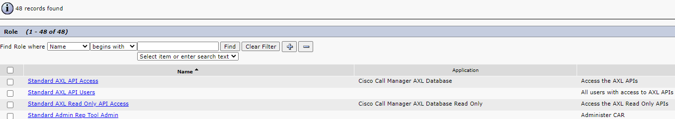
Select the checkbox for the following roles, then click 'Add Selected':
- Standard AXL API Access.
- Standard CCM Admin Users.
- Standard SERVICEABILITY Read Only.
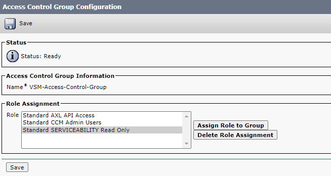
After being added, the following page will appear - click 'Save'.
Create an AXL User
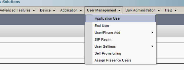
From the CUCM Administration page go to User Management > Application User > then Click 'Add New'.
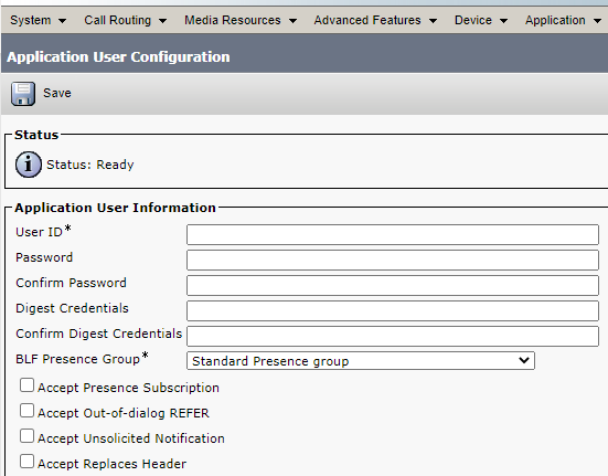
Enter user details in the Application User Information, using the following table.
Application User Information
Field | Value |
User ID | This is the user that is going to be used by VSM to access the CUCM |
Password | Enter the password for the new user. |
Confirm Password | Type the same password again. |
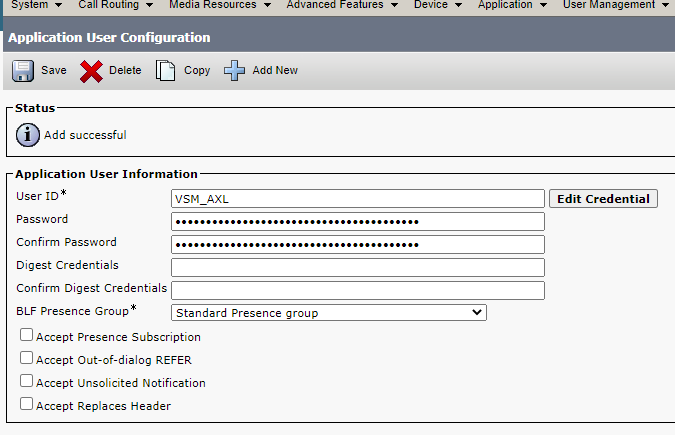
Here is an example of the form being filled out.
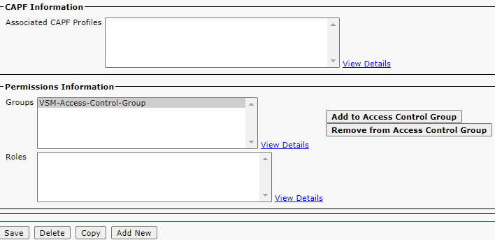
Under 'Permission Information' for the newly created Application User, click 'Add to Access Control Group'.
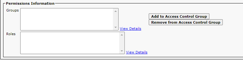
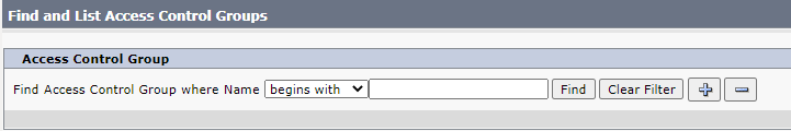
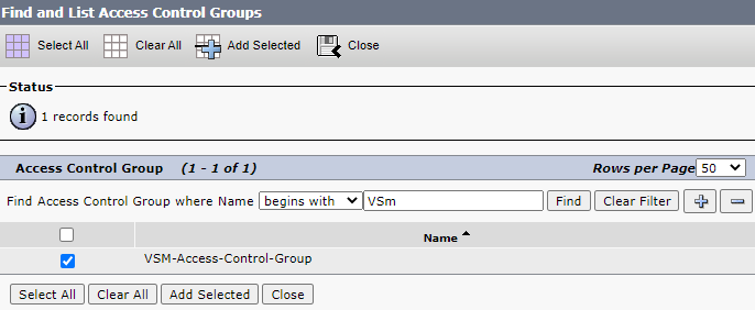
In the search bar, enter the name of the newly created Access Control Group - then click find.
Check the checkbox next to the created Access control Group and then click 'Add Selected'.
Click Save under 'Application User Configuration'.
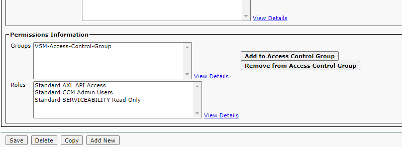
Once you click 'Save', it will show the list of roles assigned to the user.
Make sure you can sign in to CUCM with the newly created account by signing out and then signing back in with your new account.
CUCM SNMP Configuration
SNMP configuration is required as part of CUCM Monitoring. SNMP can be configured as V1, V2, or V3 based on customer requirements.
Changes to the SNMP configuration on CUCM will require a service restart to take effect.
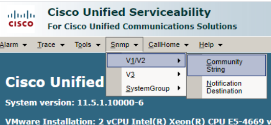
Browse to the CUCM, then select "Cisco Unified Serviceability" from the navigation menu.
Configure SNMP V1/V2
Navigate to SNMP > V1/V2 > Community String.
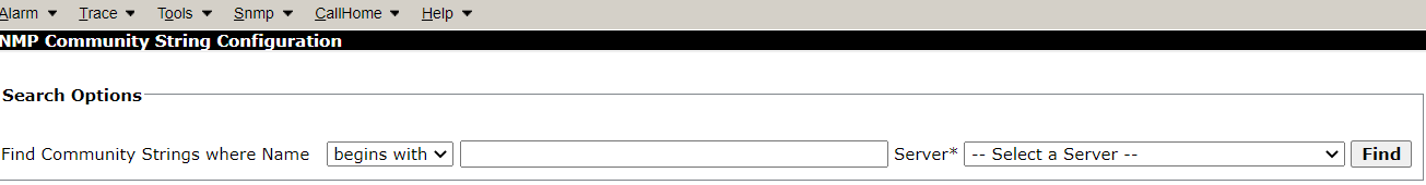
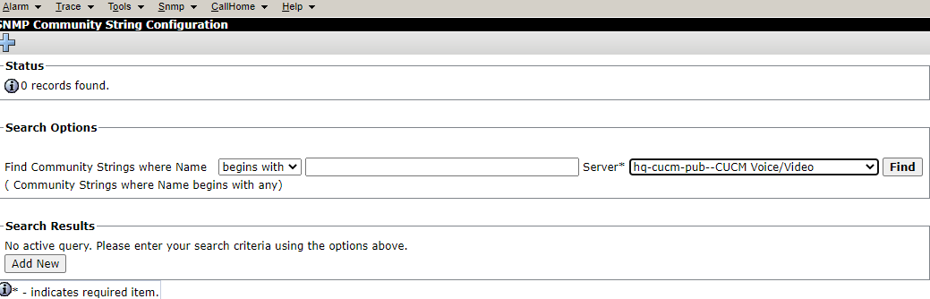
From the drop-down list, choose the server you want to configure SNMP for, then click find.
If no community strings are listed, or if you want to configure a new one, press the "Add New" button at the bottom of the page.
SNMP needs to be configured on all the servers in the CUCM Cluster.
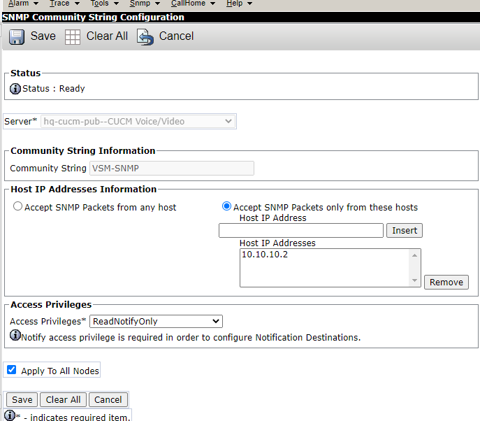
Fill in the SNMP Community String Page with the following values.
SNMP Community String Configuration
Field | Value |
Community String Name | Enter the required Name. |
Hosted IP Address Information | Choose one of the following based on the client requirements 1- Accept SNMP Packets from any host. 2- Accept SNMP Packets only from these hosts If you choose to Accept SNMP Packets only from these hosts, make sure to enter the IP Address of the VSM Probe server under Host IP Address. |
Access Privilege | Choose ReadNotifyOnly unless something else required from the customer. |
Apply to All Nodes | Check the checkbox to apply the configurations to all servers within the cluster. |
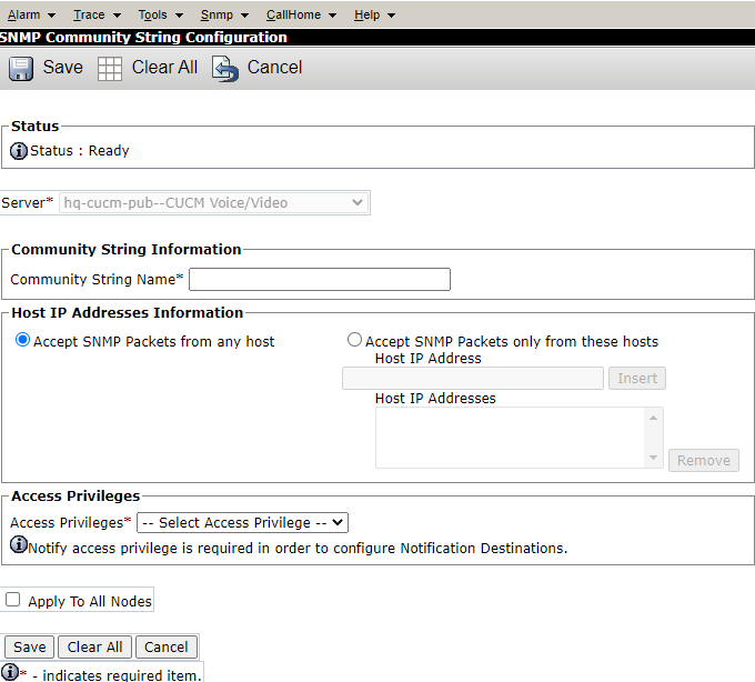
Below is an example of the form being filled out.
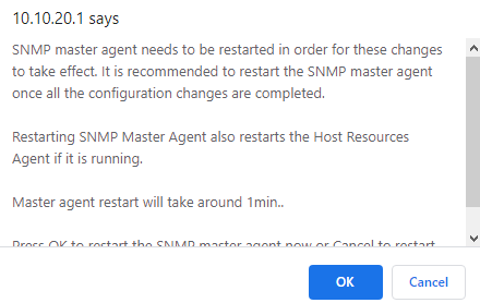
When you click save, a warning will be displayed notifying you that you need to restart SNMP Master Agent Service for the changes to take effect.
Click 'OK' to restart the service.
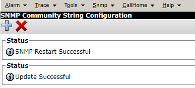
Once completed, the following message will be displayed with the status of the restart.
SNMP Traps
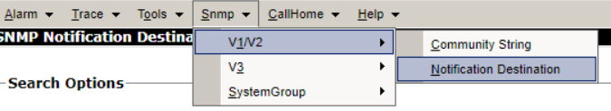
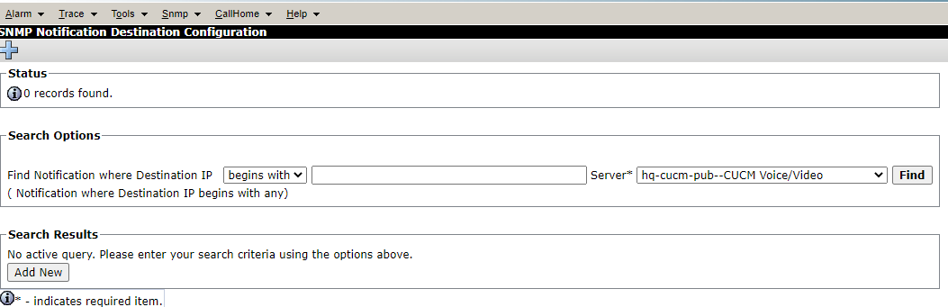
Configure CUCM to send SNMP Traps by navigating to SNMP > V1/V2 > Notification Destination.
SNMP Notification Destination
Field | Value |
Host IP Address | VSM Probe IP Address |
Notification Type | Trap |
Choose server > Find > Click "Add New".
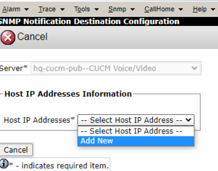
The following page appears; from the drop-down list, choose "Add New".
Enter values into the page you are taken to as per the following table.
SNMP Notification Destination
Field | Value |
Host IP Addresses | Add New is selected |
Host IP Address | VSM Probe IP Address |
Port Number | Default is 162; change it only if needed |
SNMP Version | Choose either V1/V2C |
Notification Type Information | Trap |
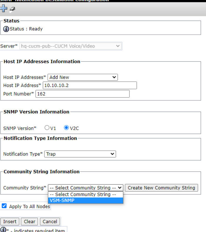
Once you choose "Notification Type", the Community String Information will be displayed.
Choose the Community String created earlier and check "Apply to All Nodes".
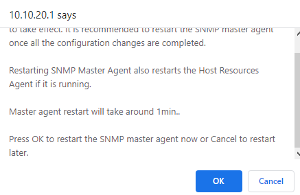
When you click 'Insert', a warning will be displayed notifying you that a restart of SNMP Master Agent Service is required for the changes to take effect.
Click 'OK' to restart the service, or press 'Cancel' if you wish to do it later.
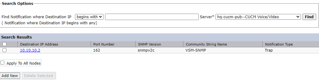
After restarting, SNMP Notification Destination Configuration will show the new Destination IP Address.
CUCM SNMP V3 Configuration
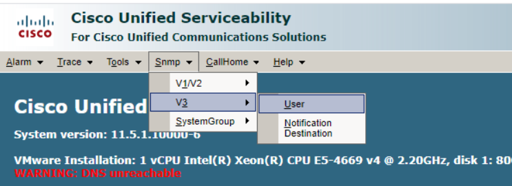
Navigate to SNMP > V3 > User.
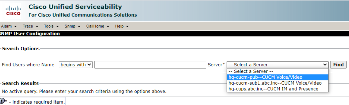
Select a server from the drop-down list and click 'Find'.
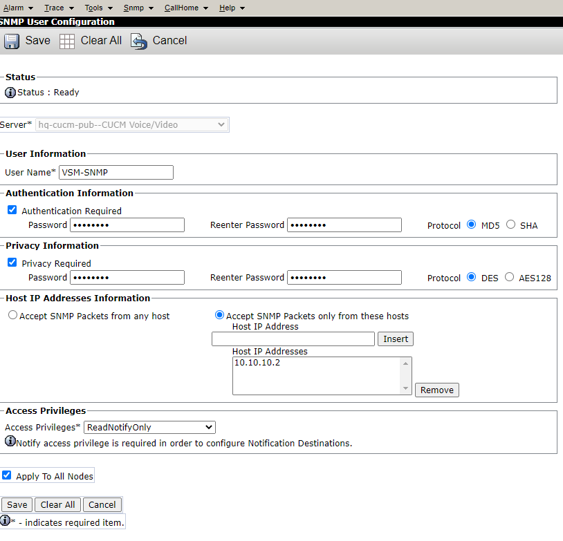
Click 'Add New' to create an SNMP User, then fill out the form using the table below.
SNMP V3 User configuration
Field | Value |
User Name | Enter SNMP User Name |
Authentication Required | Check the checkbox of Authentication |
Password | Enter the Password |
Protocol | Choose either MD5 or SHA |
Privacy Required | Optional/check the checkbox if required |
Password | Enter the password |
Protocol | Choose the preferred Protocol (DES/AES128) |
Accept SNMP Packets from any host | Uncheck the checkbox |
Accept SNMP Packets only from these Hosts | Check the Check box |
Host IP Address | Enter the IP Address of the VSM Probe and click Insert |
Access Privileges | Choose ReadNotify Only |
Apply to All Nodes | Check the checkbox |
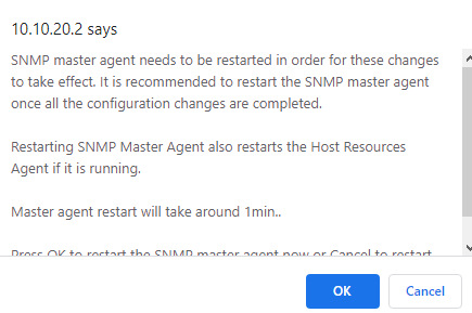
When you click 'Insert', a warning will be displayed notifying you that a restart of SNMP Master Agent Service is required for the changes to take effect.
Click 'OK' to restart the service.
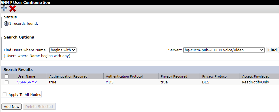
After restarting, the SNMP user configuration will be displayed with the new user configured.
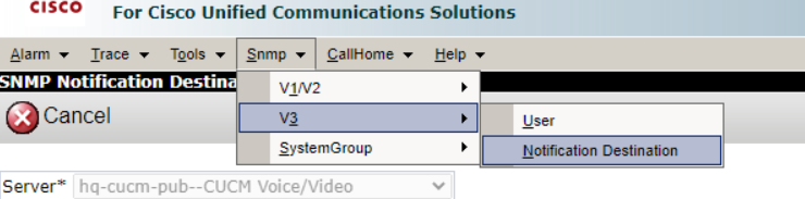
Navigate to SNMP > V3 > Notification Destination.
Choose server >Find > Click 'Add New'.
The following page will appear. From the drop-down list, choose 'Add New'.
Enter values into the page as per the following table.
SNMP Notification Destination Configuration Table
Field | Value |
Host IP Addresses | Add New is selected |
Host IP Address | VSM Probe IP Address |
Port Number | Default is 162; change it only if needed |
SNMP Version | Choose either V1/V2C |
Notification Type Information | Trap |
| Security Level | Choose based on the security level configured for the user |
| User Information | Check the checkbox next to a created user |
| Apply to All Nodes | Check the checkbox next to Apply to All Nodes |
Click Insert.

When you click 'Insert', a warning will be displayed notifying you that a restart of SNMP Master Agent Service is required for the changes to take effect.
Click 'OK' to restart the service.
CUCM Syslog configuration
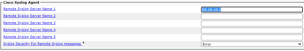
Navigate to Cisco Unified CM Administration > System > Cisco Syslog Agent > Remote Syslog Server Name.
Enter the IP Address of the VSM Probe as one of the Remote Syslog Servers.
Choose the Syslog Severity for Remote Syslog messages based on your requirements.
CDR Configuration
Navigate to Cisco Unified Serviceability.
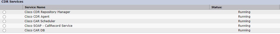
From there, navigate to Tools > Control Centre – Feature Service > Select 'Publisher' from the drop-down list.
Make sure All CDR services are up. Start the services if it was deactivated or stopped.

Navigate to Cisco Unified Serviceability > Tools > Control Centre – Network Services > Select Publisher from the drop-down list.
Make sure all CDR services are up.
Navigate to Cisco Unified Serviceability > Tools > Control Centre – Network Services > Select Subscriber from the drop-down list.
Make sure the CDR Agent service is running. Repeat the above step for all subscribers in the Cluster.

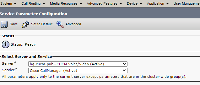
Navigate to Cisco Unified CM Administration > System > Service Parameter > Call Manager Service.
Set the 'CDR Enabled Flag' and the 'CDR Log Calls with Zero Duration Flag' to 'True'.
This must be done for all the nodes in the server, as well as all CUCM servers in the cluster.

Navigate to System > Service Parameter > Call Manager Service > Clusterwide Parameters.
Set the 'Call Diagnostics Enabled' parameter to 'Enabled Only When CDR Enabled Flag is True'.

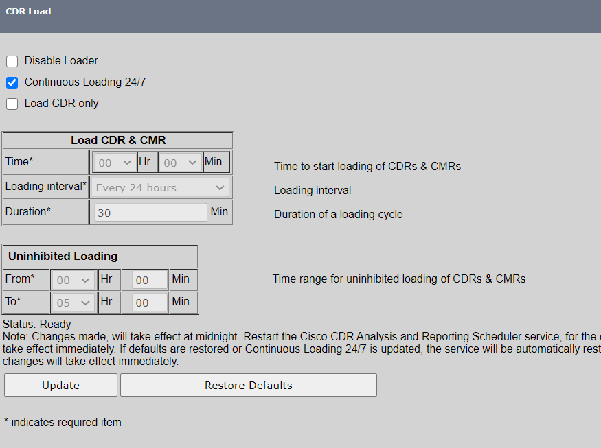
Navigate to Cisco Unified Serviceability > Tools >System > Scheduler > CDR Load
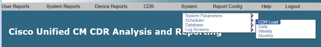
Make Sure that Continuous Loading 24/7 checkbox is selected.
Now add an SFTP server/Billing Server where the files will be sent to. Navigate to Cisco Unified Serviceability > Tools > CDR Management > Add New Billing Server.
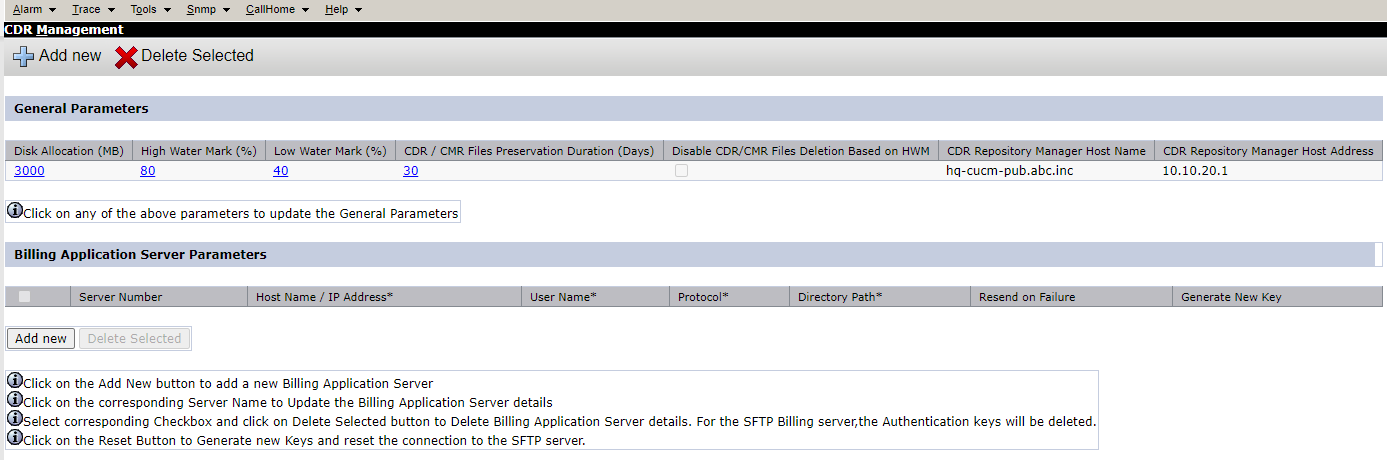
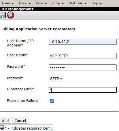
Billing Application Server Parameters
Field | Value |
Host Name /IP Address | Enter Probe IP server |
Username | Enter username details for SFTP |
Password | Enter Password details for SFTP |
Protocol | SFTP |
Directory Path | \ |
Resend on Failure | Check the checkbox |
CUCM Backup Configuration
The following is required to configure VSM as a destination for backup files. These Backup files will be sent from the VSM Probe to the Virsae Cloud.
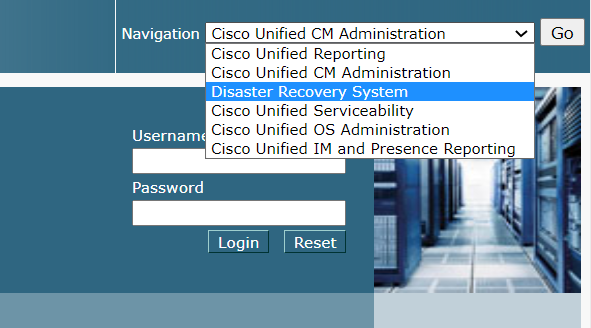
Navigate to Disaster Recovery System.
Navigate to Backup > Backup Device > Add New.
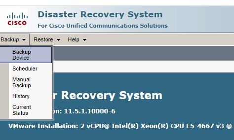
Enter the required details for the Backup Device using the details in the following table.
Backup Device Details
Field | Value |
Backup Device Name | Enter Any name |
Host name / IP Address | VSM Probe IP Address |
Path name | \ |
User name | VSM SFTP server username |
Password | VSM SFTP server password |
Number of backups to store on Directory | Leave it to default – VSM Probe will send the backups to Virsae Cloud. |
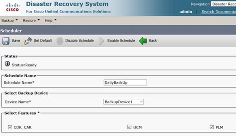
Configure backup scheduler by navigating to Backup > Scheduler.
Define a Scheduler Name. Select the Device name (the device created earlier) and check the features you want to backup; ideally, check all the options.
If using CUCM prior to Version 12.0, the features are CDR_CAR, UCM and PLM.
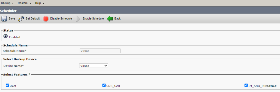
If using CUCM Version 12.0 and later, the features are CDR_CAR, UCM and IM_AND_PRESENCE.
CUCM Backup features prior to Version 12.0
CUCM Backup features for Version 12.0 and later
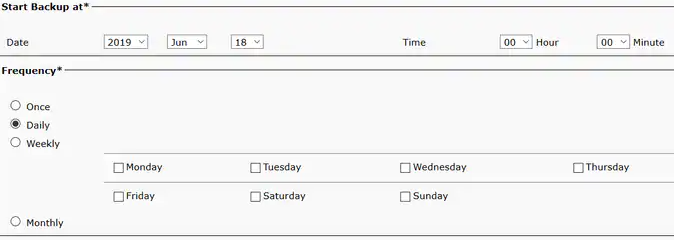
Configure a backup schedule based on your situation.
We recommended a daily backup to occur after hours.
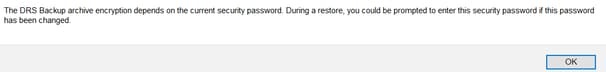
Click 'Save'. A warning message, as shown in the image below, will pop up.
Click 'OK'.
Once the Backup Schedule is created, click on Enable Schedule.
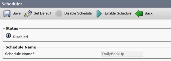
Make sure the schedule status is changed to Enabled.
Once complete you can move on to the administration in the VSM Web Portal.
Web Portal Configuration
Add CUCM
Log in to the VSM web portal using your VSM credentials and password.
For your customer, select Service Desk > Equipment Locations. Right-click on the Equipment Location (Appliance) that will serve this particular UC Server and select ‘Manage Equipment’
At the bottom of the ‘Manage Equipment’ page click on the ‘Add Equipment’ button.
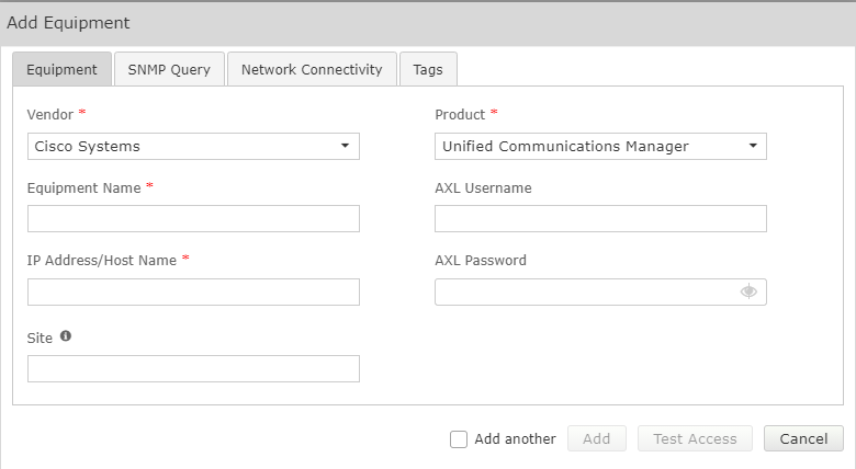
A form will open which you can populate with the equipment details as per table the table below.
Select the Vendor ‘Cisco Systems’ and Product ‘Unified Communications Manager’.
Web Portal – Add CUCM Field Description
Field | Setting |
Vendor | Cisco Systems |
Product | Unified Communications Manager |
Equipment Name | Friendly name for this CUCM |
AXL Username | AXL Username |
AXL Password | AXL Password |
IP Address / Host Name | IP Address of server |
Site | Free text field, this information will be included in alarm notifications from the VSM Workflow. |
SNMP
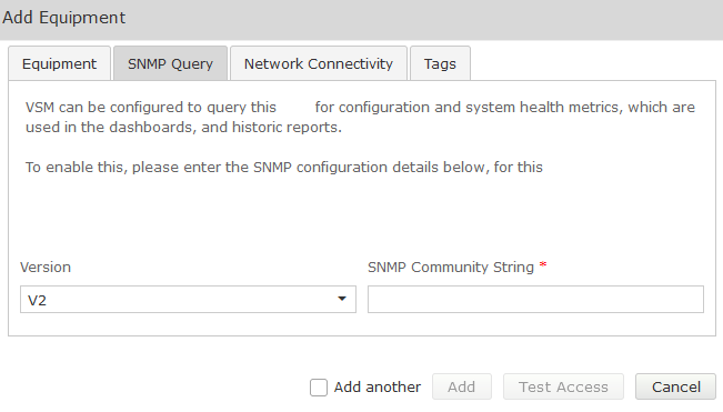
Complete the Equipment tab and then click on the ‘SNMP Query’ tab.
Click on the down arrow, and select the SNMP version you wish VSM to use for querying the CUCM:
SNMP V1 or V2
CUCM SNMP V1/V2 Field Descriptions
Fields | Setting |
Version | V1, V2 |
SNMP Community String | Community String as administered on the CUCM |
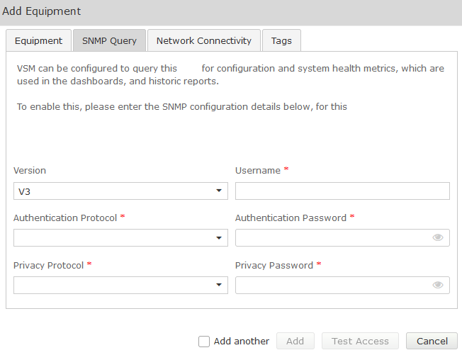
SNMP V3
CUCM SNMP V3 Field Description
Fields | Setting |
Version | V3 |
Username | SNMP V3 Username |
Authentication Protocol | SHA (recommended) |
Authentication Password | Password |
Privacy Protocol | DES (recommended) |
Privacy Password | Password |
Test Access
Once all fields are populated Click on the Test Access button. This will test that VSM can connect to the CUCM using the settings you have entered:
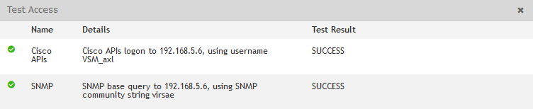
Both API and SNMP should return success. If not, troubleshoot the configuration.
Once testing is successful, click Add.