This section makes frequent use of data contained in the Technical Requirements.
All relevant sections of the Technical Requirements Data collection should be completed or known before commencing with the steps in this section.
There are two parts to the configuration, the first being the server(s) under management, and the second being the supporting configuration on the web portal.
Both are covered in this chapter.
ACM Configuration
Adding a new ACM Login
The VSM Probe requires access to Avaya Communication Manager with the appropriate user rights.
This can be achieved by creating a new user within Avaya Communication Manager with user profile 18, or a read-only account with the same level of access.
Browse to the Avaya Communication Manager and log in. Click on Security > Administrator Accounts and select Add Login and Privileged Administrator and click submit:
Enter details as per the table below:
| Fields | Setting |
|---|---|
Login name | Choose a Login name (refer to technical requirements forms) |
Additional groups (Profile) | prof18 |
SAT Limit | none |
Date to disable account | Leave blank |
Password | Choose a password (refer to technical requirements forms) |
Force password change | No |

Click Submit.

Once this account has been created, test it has the correct privileges by logging onto the ACM SAT and Linux CLI and running the following non-destructive commands:
ACM SAT:
$ display system-parameters customer-options
$ list registered-ip-stations
$ list measurements occupancy summary
$ status ip-network-region
$ monitor security-violations station-security-codes
$ display alarms
$ test port
ACM Linux CLI:
$ server
$ cat /etc/opt/ecs/ecs.conf
$ pingall –s 1
$ ifconfig –a
These commands should all return valid data. If not, the account you created is not correct.
Adding a new Media Gateway Login
The VSM collector requires access to the Media Gateways.
This can be achieved either by using the existing root account or by creating a new administrator account on each Media Gateway.
To use the root account, the password needs to be added to the VSM portal and instructions are in the next section of this manual.
To add a new administrator account, refer to the completed technical requirements forms and run these commands:
G450/430:
- Logon as 'root'
Run the command:
$ Username {choose a username} password {choose a password} access-type admin- Test you can login to the Gateway with the new credentials.
G700:
- Logon as 'root'
- The prompt should be 'MG-001-1'
- Run the command: 'session stack'
- The prompt should now be 'P330-1'
Run the command:
$ Username {choose a username} password {choose a password} access-type admin- Test you can login to the Gateway with the new credentials.
SNMP Traps and Access
SNMP traps are used to capture alarms raised by Avaya Communication Manager, SNMP Access is used by VSM to query certain information from the Avaya Communication Manager.
ACM SNMP Access
The VSM collector must be allowed to query the Avaya Communication Manager via SNMP.
Click on SNMP > Access. Click on 'Add/Change'. 
Enter the details in the SNMP Version 2c or 3 option and click the Submit button:
ACM SNMP Access Field Description
| Field | Settings |
|---|---|
IP Address | IP address of the VSM collector |
Access | Read-Only |
Community Name/User Name (v3) | Choose an SNMP User Name or Community Name (refer to technical requirements forms) |
Authentication Protocol (v3) | Choose an Authentication Protocol |
Authentication Password (v3) | Choose an Authentication Password (refer to technical requirements) |
Privacy Protocol (v3) | Choose a Privacy Protocol |
Privacy Password (v3) | Choose a Privacy Password (refer to technical requirements forms) |
SNMP Traps
The VSM collector must be added as a destination for SNMP traps. For this reason, the VSM collector must be assigned a fixed IP address.
Click on SNMP > FP Traps. Enter the details in the SNMP Version 2c or 3 option and click the Submit button: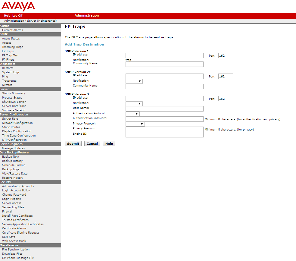
ACM SNMP Trap Field Description
| Fields | Setting |
|---|---|
IP address | IP address of the VSM collector |
Notification | trap |
User (v3)/Community Name | Choose an SNMP User Name or Community Name (refer to technical requirements forms) |
Authentication Protocol (v3) | SHA |
Authentication Password (v3) | Choose an Authentication Password (refer to technical requirements) |
Privacy Protocol (v3) | DES |
Privacy Password (v3) | Choose a Privacy Password (refer to technical requirements forms) |
Engine ID (v3) | Not required |
After adding the SNMP destination it should be listed on the FP Traps page:
Next the ACM application also needs to be configured to send INADS alarm information to VSM via SNMP. This is done via the shell command "almsnmpconf".
To use this command, log into the ACM server Linux prompt. Execute the command:
$ almsnmpconf -d {VSM collector IP ADDRESS} -c public
Where:
{VSM Probe IP ADDRESS} is the IP address of the VSM collector.
Check that the INAD SNMP alarms are enabled by executing the following command:
$ almenable
If the output is: ![]()
execute the command below to enable it:
$ almenable –s y
For customers with duplicated servers, this needs to be done on each server independently.
Modify Station SNMP Settings
To complete the SNMP configuration in Avaya Communication Manager, the VSM probe server must be added to the IP Node names table as shown below and then that Name used in the IP Options page.
This configuration allows VSM to request information via SNMP query:
ACM SNMP Node-names IP Field Description
| Fields | Settings |
|---|---|
Name | VSM collector IP node-name (refer to technical requirements forms) |
IP address | VSM collector IP Address |
Submit the form.

If the Download flag is set to yes as shown above then these settings will be downloaded to the phone and will overwrite any 46xxxSettings.txt file settings.
ACM SNMP System-parameters IP-Options Field Description
| Fields | Settings |
|---|---|
Download Flag? | Y |
Community String | SNMP Community to query phones |
Source Address | VSM collector IP node-name (refer to technical requirements forms) |
Submit the form.
SIP Stations
For SIP Stations, you will need to administer this within the 46xxSettings.txt files as follows and/or via Session Manager Device Settings Groups:
In the SNMP section edit and uncomment the following settings. Add text as per below:
SET SNMPADD {VSM collector IP Address}
SET SNMPSTRING {SNMP Community to query phones}
ACM Firewall
Ensure the Avaya Communication Manager firewall is configured to pass SNMP. Click on Security > Firewall:

ACM policy must accept UDP 161 and 162.
Enable Syslog streaming
ACM 8.0 and earlier:
The following changes are required to define the VSM collector as a destination for Avaya Communication Manager Syslog. Click on Security > Server Log Files:
ACM Syslog Field Description prior to ACM 8.1
| Fields | Settings |
|---|---|
When Submit button is clicked… | Checked |
Enable logging to the following Syslog server | Selected |
Server name | VSM collector IP Address |
Selection for which logs are to be sent | All Checked |
ACM 8.1 and later:
The following changes are required to define the VSM collector as a destination for Avaya Communication Manager Syslog. Click on Security > Server Log Files:

Administer any available 'Log Server'.
ACM Syslog Field Description For ACM 8.1 onwards
| Field | Configuration |
|---|---|
| Enabled | Yes |
| Protocol | UDP |
| Port | 514 |
| Server/IP | VSM collector IP Address |
Once the details have been entered click the Submit button.
Sat Terminal
At the SAT terminal, enter the command 'Change Logging-Levels'.
On page 1, set the 'Log Data Values' field to 'Both' and All Action Values (with the exception of Display, Get, List, Monitor and Status) to 'y'.
On page 2, set the 'Log PMS/AD Transactions' field to 'Y': 

These changes increase the logging level to add a greater level of Change Manager reporting.
ACM Logging Levels Field Description
| Fields | Setting |
|---|---|
Log Data Values | Both |
All Action Values | Y – Except 'Display' 'Monitor' 'Status' 'List' 'Get' |
Log PMS/AD Transactions | Y |
Submit the form.
Configure Off-site Backups
The following changes are required to define the VSM collector as a destination for ACM Backups.
These Backup files will be sent from the VSM collector to the Virsae Cloud.
Click on Data Backup/Restore > Schedule Backup > Add:
ACM Off-site Backups Field Description
| Fields | Setting |
|---|---|
Method | sftp (Secure File Transfer Protocol) |
User Name | Must match the SFTP Backup settings in the Web Portal Equipment Location |
Password | Must match the SFTP Backup settings in the Web Portal Equipment Location |
Hostname | VSM collector IP Address |
Directory | / |
Click 'Add New Schedule'.
Configure CDR (Optional)
Complete this section if the CDR feed from the customer will use VSM as a destination.
The more data that can be fed into VSM, the better the outcome will be.
If there is a CDR application already in use, configure the secondary CDR feed.
The following changes are required to define the VSM collector as a CDR destination.
Use the command 'Change IP-Services' and add the service type for the CDR1 or 2:

Go to page 3 and check the setting for the CDR you just configured are as shown in the image below:
ACM IP-Services Field Description
| Field | Setting |
|---|---|
Local Node | ProcR or C-Lan |
Local Port | 0 |
Remote Node | virsae |
Remote Port | 9000 |
| Reliable Protocol | N |
| Packet Response Timer | 30 |
| Session Connect Message Cntr | 3 |
| SPDU Cntr | 3 |
| Connectivity Timer | 60 |
Submit the form.
ACM System-parameters CDR
Use the command 'Change System-Parameters CDR' – using either the primary, if available, or the secondary, if the primary is in use.
Enter the output type as 'Unformatted' and names the output Endpoint CDR1 or CDR2: 
ACM CDR Field Description
| Fields | Setting |
|---|---|
Primary/Secondary Output Format (use whichever is spare) | Unformatted |
Primary/Secondary Output Format (use whichever is spare) | CDR1 or 2 |
Submit the form.
Configure RTCP for VQM
The following changes are required to define the VSM Probe as the destination for RTCP (Voice Quality) traffic from the UC environment:
ACM System-parameters IP-Options Field Description
| Fields | Setting |
|---|---|
Default Server IP Address | VSM collector IP Address |
Default Server Port | 5005 – *See Note |
Default RTCP Report Period (secs) | 5 |
Note: A single Equipment Location can support multiple RTCP Receivers.
Each individual ACM and its adjuncts should report to a separate discrete RTCP Receiver using a unique port for each.
Submit the form.
SIP Endpoints RTCP
The following settings in the 46xx Settings file are mandatory if you have SIP endpoints and you wish to receive VQM for their calls.
SET RTCPCONT
SET RTCPMON {VSM collector IP Address}
SET RTCPMONPORT 5005
SET RTCPMONPERIOD 5
After these entries have been put into the settings file you will need to restart SIP endpoints for them to take effect.
Avaya Agent For Desktop RTCP
If you are using Avaya Agent for desktop, the RTCP settings need to be set on each client using the following steps:
In the system tray, right-click the Avaya Agent for Desktop icon and select Configuration.
The system displays the Avaya Agent for Desktop Configuration window.
- In the Avaya Agent for Desktop Configuration window, select the Advanced tab.
- In the RTCP Monitoring Server Settings section, perform the following actions:
- In the Address field, type the IP address of the VSM collector.
- In the Port field, type the port number of the VSM RTCP receiver.
- In the Period field, enter ‘5 seconds’.
- Click Save.
ADDING: Avaya OneX Agent/Communicator
Web Portal Configuration
Add ACM
Log in to the VSM web portal using your credentials and password.
For your customer, select Service Desk > Equipment Locations.
Right-click on the Equipment Location (Collector) that will serve this particular UC Server and select 'Manager Equipment'.
At the bottom of the 'Manage Equipment' page click on the 'Add Equipment' button.
A form will open which you can populate with the equipment details using the table below.
Select the Vendor 'Avaya' and product 'Communication Manager'.

If you are adding more than one piece of the same equipment type, check the 'Add another' box at the bottom of the form and the bulk of the configuration will be carried over for the next item.
Web Portal – Add ACM Field Description
| Field | Setting |
|---|---|
Vendor | Avaya |
Product | Communication Manager |
Equipment Name | Friendly name for this ACM |
Username | ACM Username |
Password | ACM Password |
Username for Media Gateways | Media Gateway Username |
Password for Media Gateways | Media Gateway Password |
IP Address / Host Name | IP Address of server (Virtual IP of duplicated CMA/CMB servers) |
Site | Friendly name for core site (where this server is located) |
Monitored IP Network Regions | Up to 10 Intervening IP Network Regions, comma-separated |
Disable automatic connection to Media Gateways | Check this to stop VSM accessing enhanced Media Gateway service information |
Use the above credentials for all Media Gateways | Unchecking this box allows you to set different credentials for all media gateways |

SNMP
Complete the Equipment tab and then click on the 'SNMP Query' tab.
Click on the down arrow, and select the SNMP version you wish VSM to use for querying the ACM:
SNMP V1 or V2

ACM SNMP V1/V2 Field Descriptions
| Fields | Setting |
|---|---|
Version | V1, V2 |
SNMP Community String | Community String as administered on the ACM |
SNMP V3

Table 15 – ACM SNMP V3 Field Description
| Fields | Setting |
|---|---|
Version | V3 |
Username | SNMP V3 Username |
Authentication Protocol | SHA |
Authentication Password | Password |
Privacy Protocol | DES |
Privacy Password | Password |
Under the 'Avaya Phones' section enter the SNMP Community String to be used for querying phones (administered earlier in ‘System-Parameters IP-Options, and the 46xx settings file.
Also administered via Session Manager if applicable) then click the '+' button.
Test Access
Once all fields are populated Click on the 'Test Access' button. This will test that VSM can connect to the ACM using the settings you have entered:
Both SSH and SNMP should return success. If not, troubleshoot the configuration.
- The SSH test ensures the VSM collector can connect to, and log in using the account configured.
- The SNMP test ensures an SNMP query can be run.
Once testing is successful, click Add.
Testing Alarm Receipt
In the 'Manage Equipment' page, right-click on the ACM you just added and select 'Generate Test Alarm': 
The command should execute successfully. If not, troubleshoot the configuration.
Return to the home page. For the particular customer, select Availability Manager > Manage Alarms.
The Test should show as an alarm. If not, troubleshoot the SNMP Trap configuration.
This test has ACM generate an SNMP trap and ensures VSM receives the same.
Configure Site Mapping (Optional)
VSM uses the IP Network Region names in Reports and Alarms.
Sometimes the name assigned to the IP Network Region in the ACM configuration is not meaningful to the Business Partner and VSM’s Site Mapping feature allows you to customise this.
Site Mapping will only be available after VSM has performed its initial data collection on the ACM, therefore it is recommended that this is a ‘day 2’ administration.
Navigate to the customers ‘Manage Equipment’ page, right-click, and select ‘Edit’ on the ACM you wish to add site mapping for.

On the ‘Edit Equipment’ page, you should see a list of the IPNR’s and IPNR Names as administered in the ACM.

If you wish to customize the IPNR Name, click the Pen button.
Add your preferred values in the ‘Customized IPNR name’ field for the IPNR, then click on the tick.

After updating all site mappings click ‘Save’.
Serial Port Setting (Optional)
It is possible to receive data from ACM equipment using a serial connection between the equipment and the VSM Collector.
To enable this option in the VSM web portal check the "User Serial Port" checkbox.

This will bring up the Serial Port Configuration box.

Fill in the fields of the box using the information in the table below.
| Field | Setting |
|---|---|
| Comm Port | The communication port of the serial connection on the VSM Collector side. |
| Data Bits | The number of bits to send in each packet (7 or 8). |
| Stop Bits | The number of stop bits to send in the packet (max 2.) |
| Baud Rate | Frequency of bits sent along the serial connection. |
| Parity | Parity setting used for error detection. |
Serial connection settings in VSM must match the port settings listed for the serial connection by the OS.